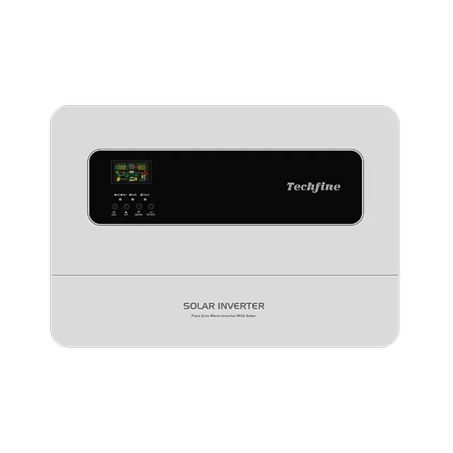
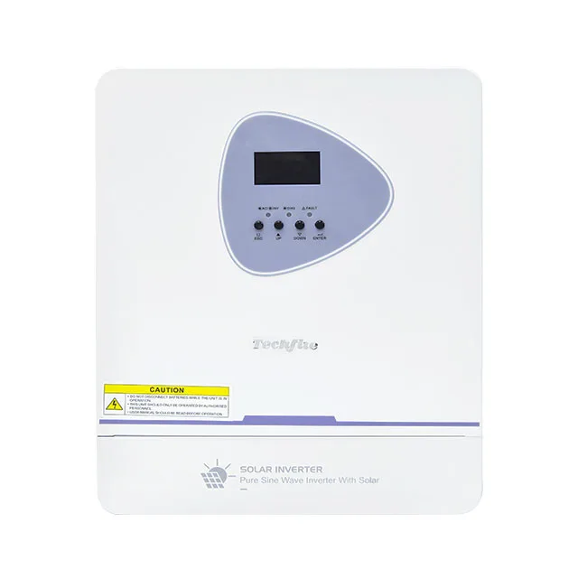
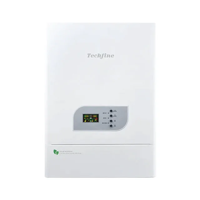
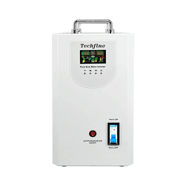
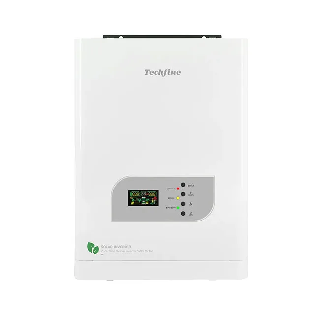
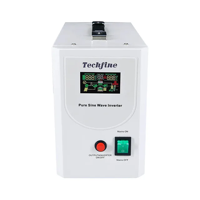
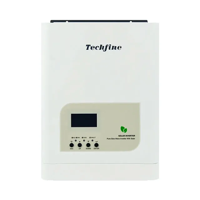
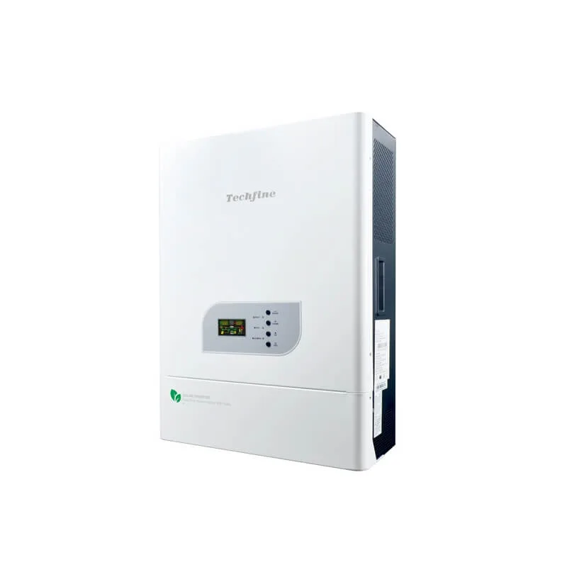
Off Grid Solar InverterJV-series | 3kW/4kW/5kW high PV off-grid solar inverter with MPPT charger
Low no-load loss, less than half of the high-frequency machine with the same power
Open the exact family page, then confirm continuous/peak output, PV charger, battery bank, AC/generator/parallel design, documents, current availability and order terms.
Off Grid Solar InverterLow no-load loss, less than half of the high-frequency machine with the same power
Off Grid Solar InverterMultiple parameters can be adjusted according to user needs to adapt to different occasions
Off Grid Solar InverterParallel Function Up to Maximum 9 units
Off Grid Solar InverterPure sine wave output
Off Grid Solar Inverter• Split-phase inverter
The eight pages range from smaller inverter-chargers to split-phase and parallel-capable families. Compare only on a common duty basis.
Displayed pages cover 1.6–5 kW-class names with MPPT charger wording. Confirm continuous/peak output, AC voltage, PV range/current, battery voltage/charge current, load behavior and exact options.
These pages span PWM or MPPT charger descriptions and broader W/VA family labels; VS PRO PLUS mentions parallel capability. Verify exact model, controller, unit count, communication and common AC/battery topology.
Two HB pages cover different VA ranges and generator-related wording. Confirm transfer/bypass, generator voltage/frequency window, start signal behavior, charge current, battery bank and load compatibility.
The VS-N page displays 110/220 Vac and 3–10 kW wording. Confirm split-phase output, neutral/grounding, leg balance, continuous/peak power, transfer, generator and destination electrical requirements.
A useful shortlist begins with actual loads, autonomy and energy sources rather than a headline kW or kVA value.
List continuous and daily loads, operating hours, simultaneous demand, motor/compressor starts, surge duration, sensitive electronics, power factor and planned growth; separate essential from deferrable loads.
Provide Wh/kWh per day, outage or no-sun duration, reserve SOC, seasonal profile and acceptable generator runtime; include inverter, cable, battery, temperature and aging losses.
Provide module data, temperatures, string plan and array power; verify cold Voc, MPPT/PWM operating range, input current, controller rating, clipping basis and available solar charging hours.
Define chemistry, nominal/operating voltage, usable kWh, current, series/parallel layout, BMS or charge profile, low-temperature limits, cables/fuses and utility/generator/solar charging current.
Confirm single/split-phase voltage/frequency, neutral/grounding, transfer/bypass, generator size/window/start, output leg balance, permitted parallel count, communications and protection.
Request exact datasheet/manual, continuous/peak test basis, settings, warranty, accessories, certificate/test scope, labels, packaging, MOQ, sample, lead time, current model status and substitution control.

Runtime and reliability depend on loads, PV resource, battery, charging, generator, environment, wiring and exact model limits.
Surge capability must include duration, voltage/frequency tolerance, temperature and load type. Do not size motors or whole sites from a peak or family headline alone.
Motor starts, nonlinear loads, power factor, neutral current, leg balance and transfer behavior still require calculation and representative testing on the exact model.
Tracking efficiency wording does not include module temperature, shading, controller/inverter losses, battery charge/discharge, wiring, curtailment or generator energy. Use a complete energy model.
Unit count, firmware, communication, common battery, AC bus, bypass, generator controls and protection are model-specific and require the exact manual and commissioning plan.
Use the remote solution for energy-system context and the compatibility guide for battery, BMS and charging interfaces.
Review how loads, PV, batteries, inverter/charger, generator, protection and local installation form one stand-alone power system.
Review microgrid context
Review voltage/current, charge profile, BMS, firmware, cables, protection and commissioning before fixing the battery bank.
Review compatibility
These answers support procurement; final load, PV, battery, generator and electrical design remain site- and model-specific.
Use simultaneous continuous loads, motor/start peaks and duration, daily energy, AC phase/voltage, autonomy, PV resource, battery current/energy, generator strategy, losses, temperature and growth. Do not select from headline kW or kVA alone.
No. Check module cold Voc, operating voltage, input current, controller power/current, temperature, string arrangement and clipping limits for the exact model. Also model available solar energy and battery charging needs.
No. These functions are family- and model-specific. Confirm permitted quantity, communication and firmware, AC/battery topology, generator input and start interface, bypass/transfer, protection and commissioning.
Include destination, exact model/rating, load schedule and surge, daily kWh/autonomy, PV strings, battery chemistry/voltage/BMS, AC phase/voltage, generator/parallel scope, files, quantity, sample and delivery target.
Compare eight displayed source pages across JV, EA, VS PRO PLUS, two HB, VS PRO, VS and VS-N split-phase routes. Source names span different W/kW, VA/kVA, PV charger, PWM/MPPT, parallel, generator and AC-output descriptions; they are not one interchangeable platform. Start with the load and daily-energy profile, then confirm exact continuous/peak output, phase/voltage, PV voltage/current and controller, battery bank and charging, generator/bypass/transfer, parallel design, protection, environment, documents, availability and commercial terms.
Send the loads and surge, daily energy/autonomy, PV array, battery bank, AC/generator/parallel design, exact series, files, quantity and schedule.