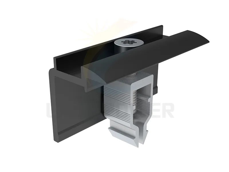
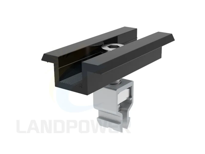
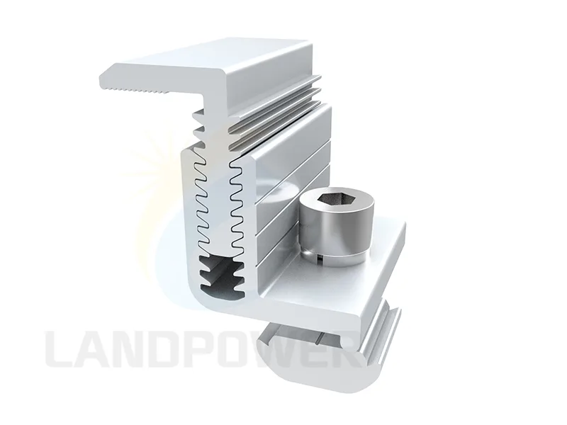
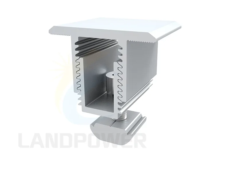
BOM compatibility checks
A controlled accessory BOM preserves the exact interface and evidence from approved design through quotation, packing, installation and replacement.
Parent system and function
Identify the roof/ground/rack system, drawing and BOM line plus whether the part provides support, clamping, fastening, splicing, cable retention, drainage assistance, bonding or another defined function.
Geometry and dimensions
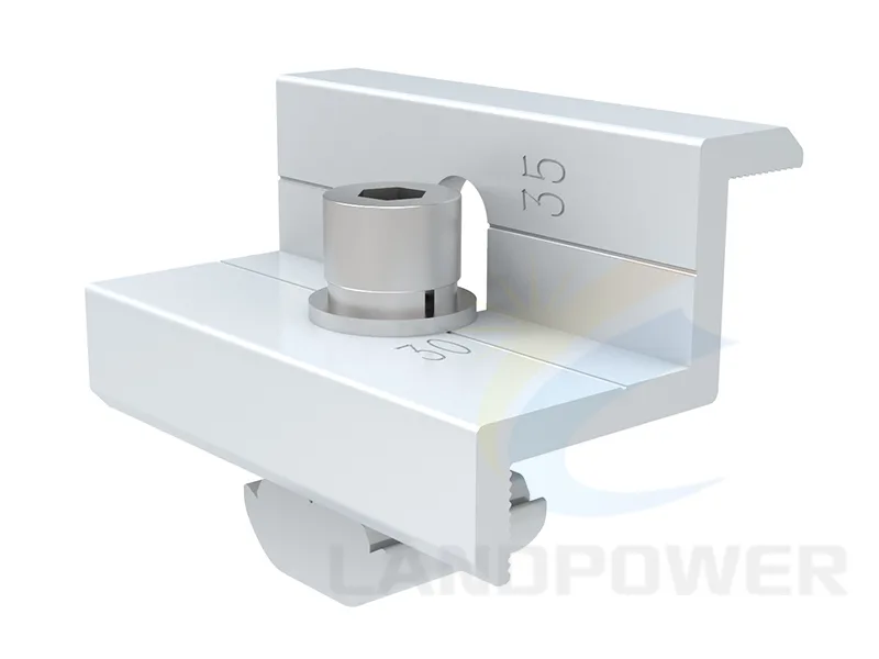
Provide rail/profile/slot, holes, threads, clamp range, module frame, cable size, substrate thickness, ground-screw head and all mating dimensions; do not approve from product photos.
Materials and corrosion
Confirm alloy/temper or steel/stainless grade, coating/anodizing, plated or bimetal construction, washers/seals, galvanic contacts, cut edges and atmospheric/soil exposure.
Loads, torque and installation
Provide the design action and evidence basis, fastener engagement, edge distance, pull-out/shear or clamp demand, tightening/installation torque, tools, sequence, inspection and reuse restrictions.
Module, cable and water interfaces
Check module manufacturer clamp/support guidance, bonding, cable bend/abrasion/UV, connector clearance and drainage-clip fit; accessories cannot override equipment instructions.
Documents, quantities and substitutions
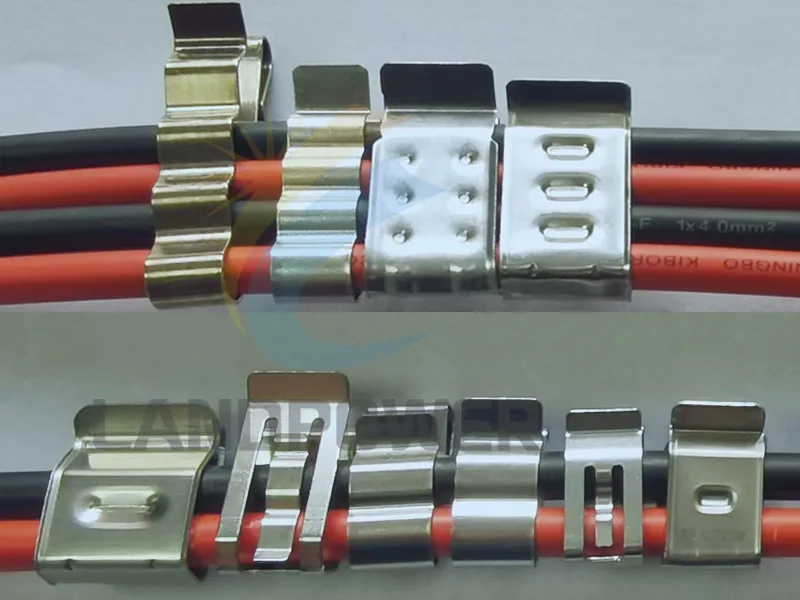
Request exact item number, dimensioned drawing, material/coating record, test/calculation scope where applicable, installation guidance, quantity by BOM line, packaging, spares and written substitution approval.
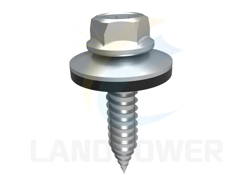 Solar Mounting Accessories