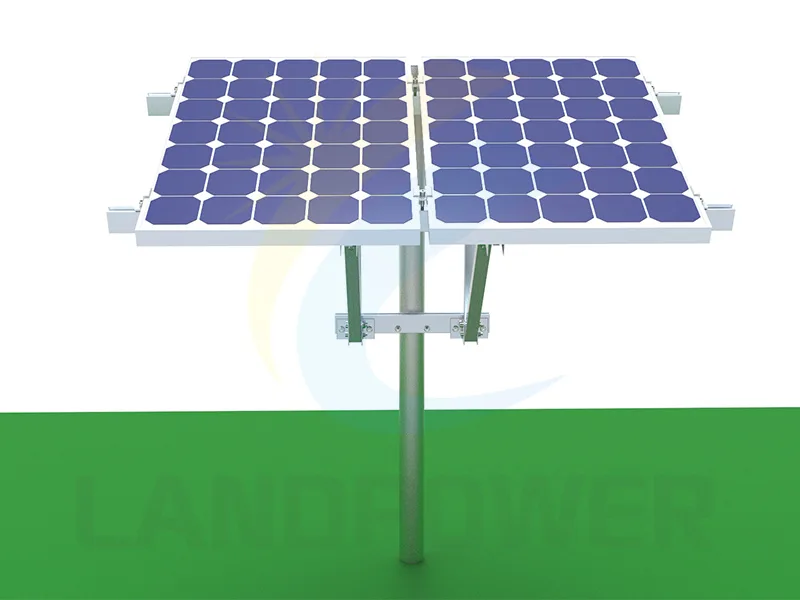
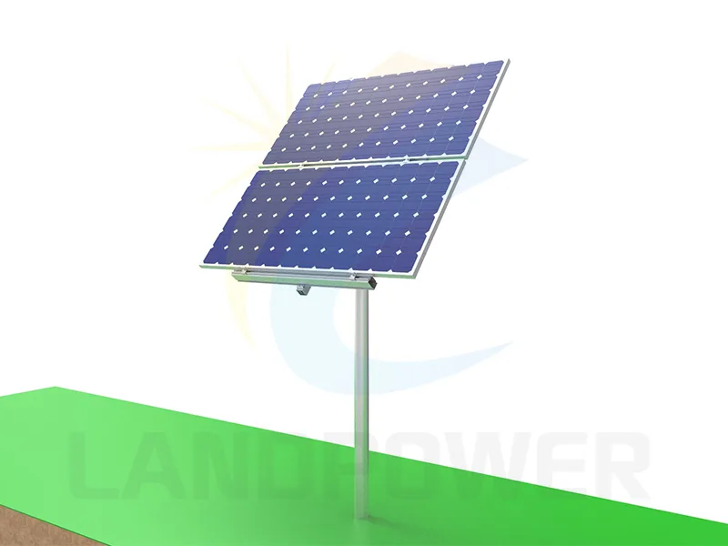
Pole MountingSide of Pole Mount Adjustable Pitch
The Solar Panel Side of Pole Mount is easy and fast solution to mount the solar panel to poles,there are two way adjustable on angles,flexible for using both in landscape or portrait.
Open the top-of-pole or adjustable side-of-pole page for available catalogue fields. Confirm the exact item, module area, approved pole interface, foundation, loads, documents and order scope in the RFQ.
Pole MountingThe Solar Panel Side of Pole Mount is easy and fast solution to mount the solar panel to poles,there are two way adjustable on angles,flexible for using both in landscape or portrait.
Pole MountingThe Top of Pole Mount is specially design for solar pump,remote WIFI and Telecom stations,with single hot galvanized steel pole and angle adjustment design for different conditions.
The two catalogue products serve different geometries. Neither route establishes the capacity of an existing pole or foundation without project verification.
Review bracket offset, permitted pole diameter or section, clamp or bolt geometry, module size, approved tilt positions, locking, torsion, rotation, tool access and cable movement.
Confirm pole-head connection, array centroid, module count and orientation, tilt, cantilever and torsion, erection/lifting method, access and protection of cables entering or running down the pole.
If the pole is in supply, define material, section, length, coating, base or embedment, foundation interface, tolerances, access openings, bonding and the responsible civil/structural design.
Record pole material, dimensions, wall thickness, joints, corrosion, previous loads, foundation and ownership. Do not assume a lighting, telecom or utility pole has spare structural capacity.
Define the array and the entire pole-foundation system so the bracket is not reviewed in isolation.
State the use—remote power, pumping, lighting, monitoring or another compact array—plus location, terrain, exposure, access, security, people nearby and maintenance constraints.
Provide exact module dimensions, mass, frame and mounting guidance, module count, portrait/landscape orientation, total projected area, cable arrangement and equipment attached to the pole.
Provide pole material, section, diameter or width, wall thickness, height, taper, joints, base/embedment, corrosion condition, photos/drawings and whether drilling or clamping is permitted.
Provide foundation drawings or site/geotechnical information, soil and groundwater conditions, embedment or base details, buried services, excavation limits and the responsible verification route.
Provide governing wind, snow, seismic and maintenance loads, allowed tilt positions, eccentricity, torsion, anti-rotation and locking requirements plus safe adjustment/installation method.
Specify coatings and fasteners, galvanic/corrosion environment, protected cable route, bonding, drawings, calculations where included, installation/torque guidance, labels, packing and spares.

Pole mounting concentrates wind and eccentric loads into a compact support. Final suitability depends on the exact array, connection, pole, foundation, site and adjustment procedure.
Original use, section loss, joints, base, foundation, previous equipment and ownership restrictions affect spare capacity. A compatible diameter does not prove structural suitability.
Side mounts and tilted arrays can create bending, torsion and rotation demands. Use the actual array area, offset, height, tilt, exposure and load combinations in the responsible calculation.
Only approved positions, locking hardware and procedures should be used. Changing tilt can change clearance, loads, fastener demand, cable movement and safe access.
A bracket rating does not approve the pole base or soil. Foundation type, geometry, reinforcement/embedment and ground response require project evidence and local design.
Use the remote microgrid solution to frame equipment and operating context, then control the bracket, pole, foundation and document lines in the project BOM.
Review how PV, storage, power conversion, loads, controls, site conditions and local design responsibilities are coordinated for remote applications.
Review solution context
Record the exact mount, pole, foundation, fasteners, cables, documents, exclusions and unverified site assumptions for a comparable quotation.
Read the buyer guide
These answers support a shortlist; final pole, foundation, structural, electrical, installation and safety approval remains project-specific.
Not on fit alone. Confirm the pole material, section and wall thickness, height, joints, corrosion, base and foundation, previous equipment, ownership restrictions, module area, offset, tilt and site loads. The responsible party must verify spare capacity and the connection.
They place the array and connection differently. That changes the centroid, eccentricity, bending, torsion, rotation, pole-head or side connection, cable route, lifting, service access and possible module count. Compare the approved complete-system design, not only bracket shape.
No. Use only documented positions and locking arrangements for the exact product and approved design. Tilt changes projected area, loads, clearances, fastener demand and cable movement, and adjustment needs a safe procedure.
Include application and site, exact module and array area, pole drawings/dimensions/condition, foundation or ground information, mount position and tilt, governing loads and code, materials/corrosion, cable route, drawings/calculations required, installation access, quantity and destination.
Compare two displayed routes: an adjustable side-of-pole mount and a top-of-pole mount. Position on the pole changes the load path, eccentricity, rotation risk, service access and cable route. Confirm the exact module area and mass, pole section and condition, bracket geometry, permitted tilt, wind/snow design, foundation capacity, corrosion, fasteners, locking, installation method, documents and project responsibility before selection.
Send the application, module count and dimensions, pole section and condition, foundation or ground data, mount position and tilt, loads and code, materials, cable route, document scope, quantity and destination.