Deye modular C&I energy-storage architecture review
Deye 100/125kW to 2.5MW C&I ESS with BOS-B Pro-A3 Battery
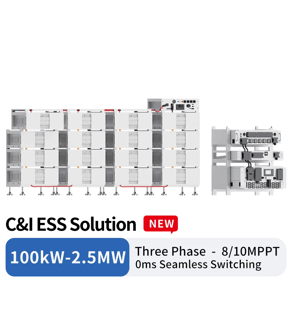
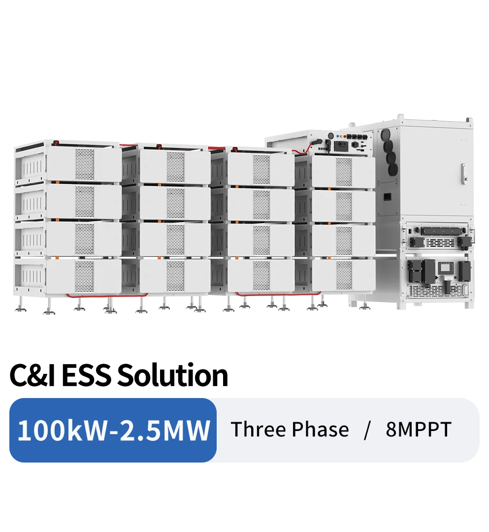
This official Deye architecture combines SUN-100K-PCS01HP3 or SUN-125K-PCS01HP3 power-conversion modules with optional 200 kW MPPT modules, a 500 kW SUN-STS500L transfer module and BOS-B Pro-A3 battery clusters. It is a scalable system concept, not one fixed 100 kW-2.5 MW bill of materials. A quotation must freeze PCS quantity, STS grouping, PV modules, battery-cluster quantity and matching mode, controls, switchgear, enclosure and site scope before price or performance is compared.
Current source identity: official Deye 100/125kW-2.5MW C&I ESS brochure dated 2026-06-22 for the 500 kW STS and BOS-B Pro-A3 architecture. A separate similarly named catalogue route uses a different 80 kW AC-DC configuration and must not be merged with this page.
Current Source Specification Tables
These tables preserve the current catalogue and official source record. Confirm the exact member, revision and destination-specific documents before order release.
MPPT Module SUN-MPPT-L01-EU-AM8
| MPPT Module | SUN-MPPT-L01-EU-AM8 |
|---|---|
| PV String Input Data | |
| Max. PV access power(kW) | 200 |
| Max. PV Input Power(kW) | 160 |
| Max. PV Input Voltage (V) | 800 |
| Start-up Voltage (V) | 200 |
| MPPT Voltage Range (V) | 180-750 |
| Full Load MPPT Voltage Range(V) | 450-750 |
| Rated PV Input Voltage (V) | 600 |
| Max. Operating PV Input Current (A) | 40+40+40+40+40+40+40+40 |
| Max. Input Short-Circuit Current (A) | 60+60+60+60+60+60+60+60 |
| No. of MPP Trackers | 8 |
| Efficiency | |
| Max. Efficiency | >99% |
| MPPT Efficiency | >99.9% |
| Equipment Protection | |
| DC input reverse protection | YES |
| DC ARC protection | Optional |
| Anti-PID(Potential Induced Degradation) | Optional |
| DC Input Switch | YES |
| Surge Protection Level | TYPE II |
| General Data | |
| Ingress Protection(IP) Rating | IP65 |
| Over Voltage Category | OVC II |
| Cabinet Size[W×H×D] (mm) | 543x198x700 |
| Weight (kg) | 41.75 |
| Type Of Cooling | Intelligent air cooling |
| Safety EMC/Standard | IEC/EN 62109-1 |
| DC Output Current(A) | |
| DC Output VoltageRange ( V ) | 630-1000 |
| Max. DCOutput Current ( A ) | 200 |
STS Module
| STS Module | SUN-STS500L |
|---|---|
| Grrid/PCS Side Data | |
| Rated AC Input/Output Active Power(kW) | 500 |
| Rated AC Input/Output Current(A) | 758/725 |
| Rated Input/Output Voltage(V) | 220/380, 230/400 (three phase) |
| Grid Connection Form | 3L/N/PE |
| Rated Input/Output Grid Frequency | 50Hz/60Hz |
| Load Side Data | |
| Rated Output Active Power(kW) | 500 |
| Rated Output Current(A) | 758/725 |
| Rated Output Voltage(V) | 220/380, 230/400 (three phase) |
| Grid Connection Form | 3L/N/PE |
| Rated Output Grid Frequency | 50Hz/60Hz |
| GEN Side Data | |
| Rated AC Input Active Power(kW) | 500 |
| Rated AC Input Current(A) | 758/725 |
| Rated Input Voltage(V) | 220/380, 230/400 (three phase) |
| Grid Connection Form | 3L/N/PE |
| Rated Input Grid Frequency | 50Hz/60Hz |
| General Data | |
| Off grid switching time | <10ms |
| Ingress Protection(IP) Rating | IP20 |
| Over Voltage category | OVC III |
| Cabinet Size[W×H×D] (mm) | 543x575x671 |
| Weight (kg) | 108 |
| Type Of Cooling | Natural Cooling |
| Safety EMC/Standard | IEC/EN 61439-1/-2 |
PCS Model
| PCS Model | SUN-100K-PCS01HP3 | SUN-125K-PCS01HP3 |
|---|---|---|
| Battery Data | ||
| Battery Type | Lithium-ion | |
| Battery Voltage Range (V) | 630-1000 | |
| Max. Charging Current (A) | 175 | 200 |
| Max. Discharging Current (A) | 175 | 200 |
| Charging Strategy for Li-ion Battery | Self-adaption to BMS | |
| Number of Battery Input | 1 | |
| DC Input Data | ||
| DC Input Voltage Range(V) | 630-1000 | |
| Max. DC Input Current(A) | 200 | |
| AC Input/Output Data | ||
| Rated AC Input/Output Active Power (kW) | 100 | 125 |
| Max. AC Input/Output Apparent Power (kVA) | 110 | 125 |
| Rated AC Input/Output Current (A) | 151.6/145 | 189.4/181.2 |
| Max. AC Input/Output Current (A) | 166.7/159.5 | 189.4/181.2 |
| Rated Input/Output Voltage/Range(V) | 220/380, 230/400 0.85Un-1.1Un | |
| Grid Connection Form | 3L+N+PE | |
| Rated Input/Output Grid Frequency/Range | 50Hz/45Hz-55Hz 60Hz/55Hz-65Hz | |
| Power Factor Adjustment Range | -1~1 | |
| Total Current Harmonic Distortion THDi | <3% (of nominal power) | |
| DC Injection Current | <0.5% In | |
| Efficiency | ||
| Max. Efficiency | 98.5% | |
| Euro Efficiency | 97.8% | |
| Equipment Protection | ||
| AC Output Overcurrent Protection, AC Output Overvoltage Protection,AC Output Short Circuit Protection, Thermal Protection, Anti - islanding Protection,Insulation Impedance Detection,Residual Current Detection | ||
| Surge Protection Level | TYPE II(DC),TYPE II(AC) | |
| Interface | ||
| LCD/LED display | LCD | |
| Communication Interface | WIFI, RS485, CAN, Meter | |
| General Data | ||
| Operating Temperature Range(℃) | -40℃to -60℃,>45℃ Derating | |
| Permissible Ambient Humidity | 0-95% | |
| Permissible Altitude | 4000m | |
| Noise | <75dB | |
| Ingress Protection(IP) Rating | IP 65(PCS Module) | |
| Cabinet Size[W×H×D] (mm) | 543x310x775(Excluding connectors and brackets) | |
| Weight (kg) | 81.86 | |
| Inverter Topology | Non-Isolated | |
| Over Voltage Category | OVC II(DC), OVC III(AC) | |
| Type of Cooling | Intelligent Air Cooling | |
| Warranty | 5 Years/10 Yearsthe Warranty Period Depends the Final Installation Site of Inverter,More Info Please Refer to Warranty Policy | |
| Grid Regulation | IEC 61727, IEC 62116, CEI 0-21, EN 50549, NRS 097, RD 140, UNE 217002,OVE-Richtlinie R25, G99,VDE-AR-N 4105 | |
| Safety/EMC Standard | IEC/EN 62477-1 | |
| Model | BOS-B Pro-A3 |
|---|---|
| Main Parameter | |
| Battery Module Energy ( kWh ) | 16.08 |
| Battery Module Nominal Voltage ( V ) | 51.2 |
| Battery Module Capacity ( Ah ) | 314 |
| Module Weight Approximate ( kg ) | 126 |
| Battery Module Qty In Series ( Optional ) | 5~16 |
| Matching Mode | PCS:14-16 units for PCS on-grid applications, 15-16 units for PCS off-grid applications |
| PCS + MPPT: 16units (on/off-grid) for MPPT Open-Circuit Voltage ≤800V;15 units (on/off-grid) for MPPT Open-Circuit Voltage ≤750V; 14units (on-grid) for MPPT Open-Circuit Voltage ≤ 700V | |
| Max.System Nominal Voltage ( V ) | 819.2 |
| Max.System Energy ( kWh ) | 257.23 |
| Max.System Usable Energy ( kWh ) | 231.51 |
| Max.Charge/Discharge Current ( A) | 180 |
| Other Parameter | |
| Operating Temperature ( ℃ ) | Charge :0 ~ 55 Discharge :-20 ~ 55 |
| Storage Temperature ( ℃ ) | 0 ~ 35 |
| Thermal Management | Smart fan cooling |
| LCD Display | SOC / Fault Code |
| Status Indicator | Yellow : Battery High Voltage Power On Red : Battery System Alarm |
| Communication Port | TCP / RS485 / CAN |
| Communication With BMS | CAN |
| Humidity | 5% ~ 85% |
| Altitude | ≤3000m |
| IP Rating of Enclosure | IP20 |
| Noise ( dB ) | TBD |
| System Dimension ( W × H × D, mm ) | 2150 × 1305 × 800 |
| System Weight Approximate ( kg ) | 2240 |
| Installation Location | Rack Mounted |
| Recommend Depth of Discharge | 90% |
| Cycle Life | 25±2°C, 0.5C / 0.5C, EOL70%≥6000 |
| Warranty Period | 10 years |
| Certification | CE / IEC62619 / IEC62040 / UN38.3 |
Current document status
The official architecture brochure and component tables are available. The project still needs a frozen BOM and one-line diagram, current manuals, battery/PCS matching schedule, protection and control philosophy, site/HVAC/fire design, destination certificates, utility/AHJ approvals, FAT/SAT plan, performance basis, warranty and transport package.
Current architecture evidence
Separate component ratings from the selected project configuration
The brochure defines supported building blocks and example topology; it does not define the delivered project BOM.
PCS modules
The official table lists 100 and 125 kW PCS models, a 630-1000 V battery/DC range, 175 or 200 A charge/discharge current and 98.5% maximum efficiency.
PV MPPT module
SUN-MPPT-L01-EU-AM8 is listed with 200 kW PV access, 160 kW maximum PV input, eight trackers, 40 A operating and 60 A short-circuit current per tracker, and 630-1000 V DC output.
STS grouping
SUN-STS500L provides named grid, load, generator and PCS paths at 500 kW and a less-than-10 ms switching label. The brochure maps five 100 kW or four 125 kW PCS modules to one STS.
BOS-B Pro-A3 cluster
A module is listed as 16.08 kWh, 51.2 V, 314 Ah and 126 kg. The cluster table reaches 257.23 kWh nominal and 231.51 kWh usable with configuration-specific 5-16 module matching rules.
C&I ESS project inputs
Six decisions needed before this architecture becomes a quotation
Power, energy, PV, transfer behavior and site scope must be solved as one topology.
Load and operating objective
Provide interval load data, critical-load kW/kVA and starting duty, outage profile, export limits, tariff/demand objective, PV profile and required autonomy or reserve SOC.
Freeze PCS and STS topology
Select 100 or 125 kW PCS quantity, STS quantity/grouping, on-grid/off-grid operating modes, continuous off-grid loading, redundancy and expansion boundary on an approved one-line.
Battery-cluster schedule
Define module count per cluster, cluster count per PCS, nominal/usable energy, voltage, current sharing, BMS/PDU, rack layout, cable lengths, isolation, balancing and expansion rules.
PV and DC architecture
If MPPT modules are included, provide module/string data, tracker allocation, cold Voc/current checks, DC bus arrangement, isolators, protection and curtailment/control logic.
Site, safety and electrical scope
Define indoor/outdoor rooms or enclosures, HVAC, ingress/corrosion conditions, fire detection/suppression and AHJ route, switchgear, transformer, grounding, emergency stop and civil interfaces.
Acceptance and commercial package
Request BOM/SLD, calculations, manuals, certificates, EMS logic, FAT/SAT tests, capacity/RTE/auxiliary-load basis, warranty, transport/SDS/UN38.3 documents, spares and exclusions.
Architecture and performance boundaries
The 2.5 MW and 257 kWh labels do not describe one ready-to-order system
Scaling claims require an engineered topology, site package and stated acceptance basis.
2.5 MW is a topology ceiling
The brochure illustrates multiple PCS and up to five STS modules in parallel. It does not mean every quotation includes 2.5 MW equipment or all required balance-of-system components.
Battery parallel claims need design evidence
The example shows up to 16 battery clusters per PCS. Confirm the exact BMS/PDU topology, current sharing, cable design, protection, controls and approved configuration before adoption.
Backup duration is load-dependent
Do not use the brochure's long-duration marketing wording as a guarantee. Calculate autonomy from selected usable energy, load, auxiliary consumption, reserve, temperature and degradation.
Ingress and safety are component-specific
PCS/MPPT modules are labelled IP65 while the STS and battery cluster are IP20. Cell chemistry and aerosol wording do not replace room/enclosure, fire-code, AHJ and emergency-response evidence.
Continue the C&I ESS review
Turn the component architecture into an auditable project package
Use the solution page for responsibilities and the sizing guide for transparent power/energy inputs.
Commercial solar and storage hybrid
Define PCS, battery, controls, grid, fire, civil, commissioning and local professional responsibilities.
Review project scope →Battery and backup sizing guide
Translate load profile, usable energy, reserve, losses and operating objective into a capacity basis.
Review sizing inputs →Deye modular C&I ESS FAQ
Questions to close before freezing the 100 kW-2.5 MW architecture
The approved BOM, topology and acceptance plan must describe the same project.
Is 100kW-2.5MW one fixed Deye ESS model?
No. It is a scalable architecture built from 100/125 kW PCS, optional 200 kW MPPT, 500 kW STS and BOS-B Pro-A3 battery components. Freeze an exact BOM and one-line.
Does one battery cluster always contain 257.23 kWh?
No. That is the maximum nominal value shown for 16 modules. The official table gives different module-count rules for PCS-only and PCS-plus-MPPT configurations.
Does less than 10 ms guarantee uninterrupted operation for every load?
No. Confirm the selected STS/PCS topology, operating mode, load tolerance, continuous off-grid loading, controls, protection and site test method.
How is this route different from the similarly named Deye page?
This record maps to the brochure with a 500 kW STS and BOS-B Pro-A3 battery. The other catalogue route names a different 80 kW AC-DC configuration and requires separate evidence.
Freeze a project-specific Deye C&I ESS configuration
Send interval loads, critical loads, autonomy, PV, grid and tariff objectives, site conditions, proposed power/energy, safety/approval scope and required acceptance tests.
Start with the product, application or project information you have. We can help identify the remaining configuration, document or delivery questions before a final quotation.
Build the Deye ESS BOM