
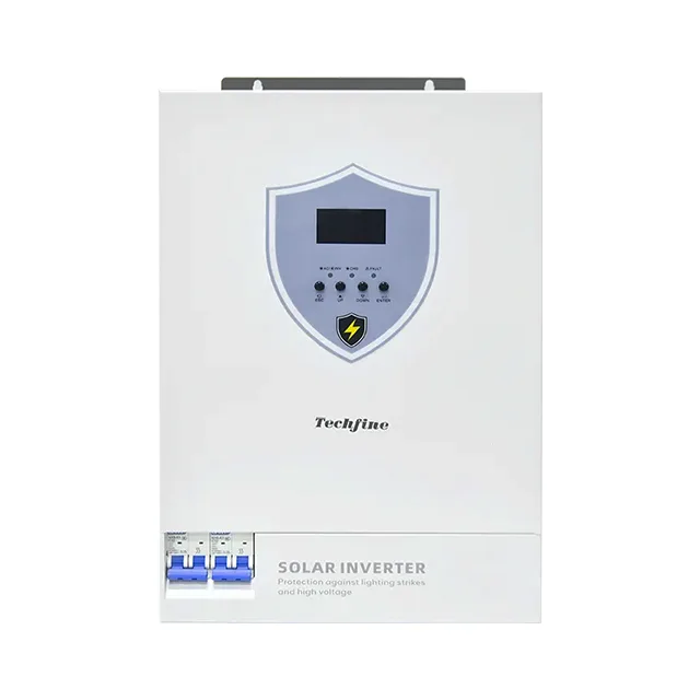
Techfine IV 4–11 kW hybrid inverter: Verify PV, Battery and AC Configuration
This page structures the current source table for the Techfine IV 4–11 kW hybrid inverter. It keeps member ratings, PV inputs, battery routes and AC data in their exact family context instead of turning a headline into a complete project design. Surge-protection title wording does not replace a site SPD design or establish the protection class supplied.
Current source record: IV 4–11 kW hybrid inverter; public table values are route evidence, not a released site design or supply schedule.
Current source parameter table
This table is preserved from the current source record. Read it with the identity, compatibility and document boundaries below; unresolved conflicts are not corrected by assumption.
| MODEL | IV4024SMH | IV6248SMH | IV11048SMH |
|---|---|---|---|
| Rated input voltage | 220/230/240VAC | ||
| Voltage range | 90-280VAC±3V(normal mode) 170-280VAC±3V(UPS mode) | ||
| Frequency range | 50Hz/60Hz(Adaptive) | ||
| OUTPUT | |||
| Battery Inverter | 4000W | 6200W | 11000W |
| Photovoltaic Inverter | 4500W | 6500W | 12000W |
| Peak Power | 8000VA | 12400VA | 22000VA |
| Output voltage | 220/230/240VAC±5% | ||
| Output frequency | 50/60Hz±0.1% | ||
| Waveform | pure Sine Wave | ||
| Switching time (adjustable) | Computer equipment 10ms, home appliances 20ms | ||
| Overload capacity | Battery Mode:11s@105%~150% Load;2s@150%~200% Load;400ms@>200% Load | ||
| GRID-CONNECTED OPERATION | |||
| Output voltage | 220/230/240VAC | ||
| grid feeding voltage range | 195-253VA | ||
| grid feeding frequency range | 49-51±1Hz/59-61±1Hz | ||
| nominal output current | 17.4A | 26.9A | 47.8A |
| power factor range | > 0.99 | ||
| maximum conversion efficiency (DC/AC) | 0.98 | ||
| BATTERY | |||
| Rated voltage | 24Vdc | 48Vdc | |
| constant voltage charging voltage (configurable) | 28.2Vdc | 56.4Vdc | |
| float charging voltage (configurable) | 27Vdc | 54Vdc | |
| PV CHARGER | |||
| PV charging method | MPPT | ||
| Maximum input power of PV | 6500W | 8500W | |
| MPPT input voltage range | 60~500Vdc | 60-500Vdc | |
| optimal Vmp operating range | 300~400Vdc | 300~400Vdc | |
| maximum PV input voltage | 500Vdc | 500Vdc | |
| maximum PV input current | 27A | 27A | 27A/27A |
| maximum PV charging current | 120A | 120A | 150A |
| maximum mains charging current | 100A | 100A | 150A |
| maximum charging current | 120A | 120A | 150A |
| DISPLAY | |||
| LCD Interface | LCD Interface:Can display operation mode/load/input/output, etc. | ||
| INTERFACE | |||
| RS232 | Baud rate 2400 | ||
| Expansion slot communication interface | Lithium battery BMS communication card, WIFI card, dry contact card, etc. | ||
| Parallel interface | No parallel function | Parallel (network) function | |
| ENVIRONMENTAL PARAMETERS | |||
| Operating ambient temperature | -10°C~+50°C | ||
| Operating environment humidity | 20%~95%(No condensation) | ||
| Storage temperature | -15°C~+60°C | ||
| noise | ≤50db | ||
| PHYSICAL PARAMETERS | |||
| Depth × width × height (mm) | 483*313*143 mm | ||
| Standards and certifications | EN-IEC 60335-1, EN-IEC 60335-2-29, IEC 62109-1 | ||
Current document status
Request the exact model/suffix datasheet, manual, nameplate, PV/battery settings, wiring diagram, firmware/options list and destination evidence before releasing an order.
Current table evidence
Match the exact member before designing the system
Power, PV, battery and AC rows can change within a family; retain the selected member throughout the RFQ.
Member and rating
IV4024SMH / IV6248SMH / IV11048SMH: 4 / 6.2 / 11 kW
AC route
The displayed table uses single-phase 220/230/240 VAC. Confirm phase, voltage, frequency, neutral/ground, generator and grid-code requirements for destination.
PV route
MPPT; 500 VDC maximum; member-dependent PV input
Battery route
The displayed battery route is 24 V or 48 V by member. Confirm chemistry, BMS protocol, current limits, temperature and approved settings.
Hybrid inverter RFQ checks
Six checks before finalizing the inverter
A complete RFQ must tie the selected member to PV strings, battery, AC loads, grid/backup operating mode and evidence.
Exact code and member
Request the full model/suffix, nameplate, revision and table row; do not quote a family power range as one released unit.
PV strings
Provide module Voc/Vmp/Imp, cold temperature, series/parallel layout, MPPT allocation, cable loss and protection; check every exact-model PV limit.
Battery and BMS
Confirm nominal voltage, usable energy, current, BMS/CAN/RS485 pairing, charge/discharge limits, settings and warranty conditions for the selected inverter.
AC and loads
Define phase, service voltage, continuous/peak load, motor inrush, critical circuits, neutral/grounding, generator and load distribution.
Grid, backup and controls
Confirm permitted grid code, export/CT/meter topology, transfer path, backup behavior, parallel route, monitoring, firmware and commissioning responsibilities.
Documents and supply
Request current manual, wiring/one-line, protection schedule, exact compliance evidence, accessories/BOM, warranty, sample, lead time and substitution controls.
Configuration boundaries
A hybrid-inverter family table is not a complete electrical scope
Project suitability depends on the exact selected member and the PV, battery, AC, protection and regulatory design.
Family boundary
Surge-protection title wording does not replace a site SPD design or establish the protection class supplied.
PV watts, Voc and MPPT differ
Rated PV watts, cold Voc and MPPT operating range are separate limits. Do not select strings from one headline number.
Battery labels are not approval
A voltage or chemistry label does not prove BMS protocol, current, charge settings, temperature behavior or warranty compatibility.
Backup and grid are project functions
Transfer timing, export control, generator behavior, parallel operation and grid acceptance require the exact manual, wiring and local project evidence.
Continue the system review
Prepare a documented hybrid-system RFQ
Use the existing system guidance to define actual loads, energy, PV strings and technical evidence.
Battery and backup sizing guide
Record usable energy, power, reserve, battery limits, loads and temperature before stating backup performance.
Review sizing inputs →Solar backup planning
Separate grid, backup and critical-load scope, then define the PV, battery and protection design.
Review backup scope →Hybrid inverter FAQ
Questions to close before quotation
The final answer must come from the selected member, current documents and installation design.
Which rating applies to this IV 4–11 kW hybrid inverter?
The current table lists IV4024SMH / IV6248SMH / IV11048SMH: 4 / 6.2 / 11 kW. Request the exact code/suffix and nameplate because family members have different electrical and PV/battery rows.
Can the inverter be paired with any battery of the displayed voltage?
No. Confirm chemistry, BMS protocol, current limits, charge/discharge settings, temperature rules, firmware and the supplier’s exact-model approval.
Does a hybrid label guarantee backup or grid export behavior?
No. Confirm AC topology, transfer path, backup loads, CT/meter/export control, grid-code configuration, generator/parallel behavior and local acceptance.
Which documents should an RFQ request?
Request exact datasheet/manual, nameplate, PV/battery settings, wiring or one-line, protection schedule, firmware/options list, compliance evidence, BOM, warranty and current commercial terms.
Prepare a verified IV 4–11 kW hybrid inverter RFQ
Send PV-string data, cold-site Voc, battery/BMS details, AC service and loads, grid/backup objective, destination and required technical documents.
Verify Hybrid ConfigurationRelated products
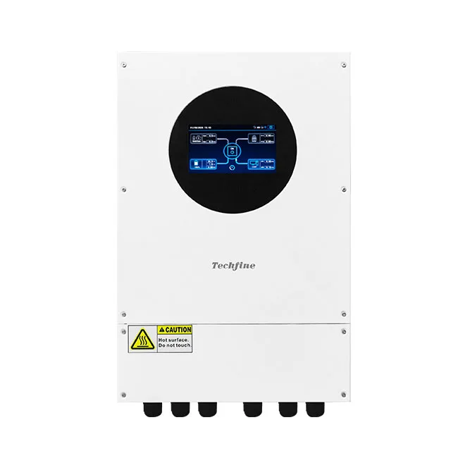 Hybrid Solar Inverter
XA-series | 6.6kW–10.6kW IP66 hybrid solar inverter support parallel
IP66 protection level
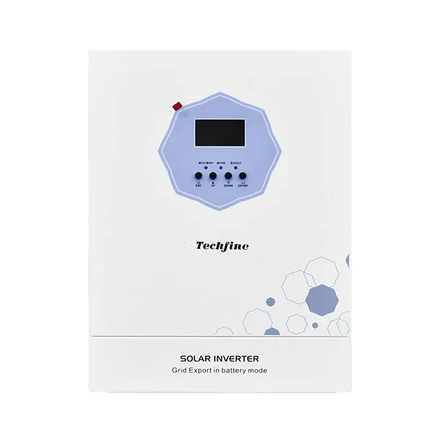 Hybrid Solar Inverter
QA-series | 3.6kW/6.2kW zero export hybrid solar inverter support CT anti-backflow
Lithium Battery Auto-Restart Function
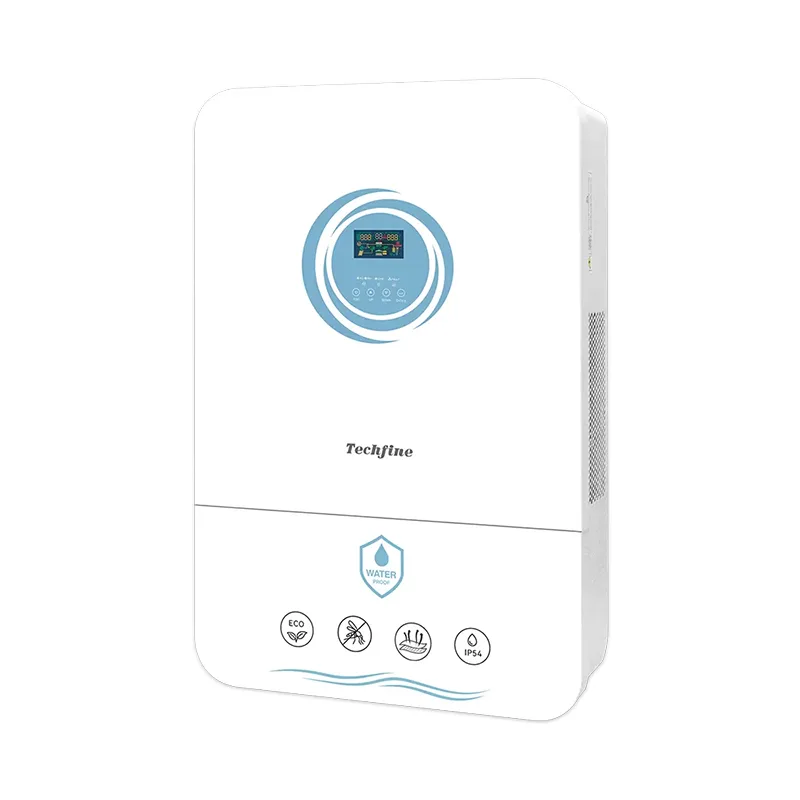 Hybrid Solar Inverter
TD-series | 4kW–11kW IP54 Rate Hybrid Solar Inverter
Higher PV input current for greater power generation