
LP-EW-T1 roof-and-ballast evidence review
LP-EW-T1 East-West Ballasted Flat-Roof Mounting for Project RFQs
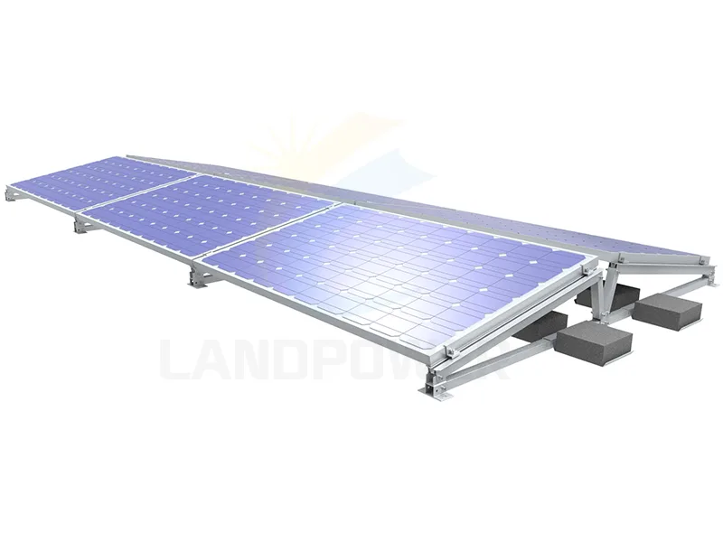
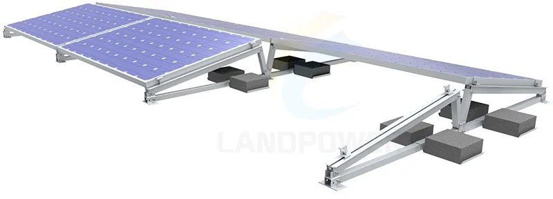
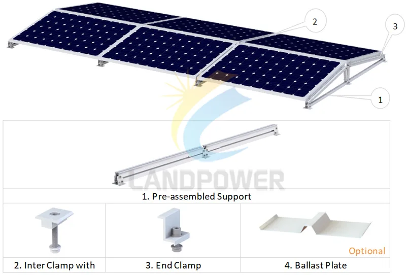
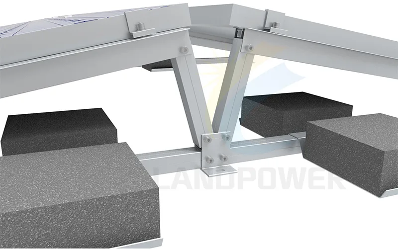
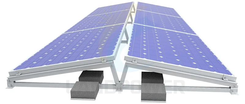
The LP-EW-T1 catalogue record describes an east-west flat- or low-pitch-roof layout with preassembled triangles, mid/end clamps, wind shield and ballast plate; an inner tube is described as an adjustable-tilt option. The introduction calls the route non-penetrating, while the detail text also permits ballast plate, concrete ballast or direct fixing with a concrete anchor. It lists 10–45°, building height up to 20 m, wind below 60 m/s, snow below 1.4 kN/m², aluminium 6005-T5, A2/304 stainless steel and EPDM. No roof-zone layout, wind basis, ballast schedule, anchor design, membrane interface or roof-capacity calculation is attached.
Current source identity: Landpower catalogue item LP-EW-T1. The non-penetrating introduction conflicts with the concrete-anchor option in the same record; no configuration drawing, zoned ballast schedule or structural evidence is attached.
Catalogue item
LP-EW-T1 / east-west flat-roof mounting
Source attachment routes
Ballast plate / concrete ballast / concrete anchor
Catalogue envelope
10–45° / height ≤20 m / wind <60 m/s / snow <1.4 kN/m²
Material labels
Al 6005-T5 / A2(304) stainless steel / EPDM
Product Details
Current document status
Request the selected ballast/anchor configuration, array and roof-zone layout, wind-test or calculation basis, zoned ballast/anchor schedule, roof reaction table, membrane separator specification, drainage/access plan, component BOM/drawings, material records, installation manual and signed warranty.
Current LP-EW-T1 evidence
Choose one defined roof-connection route before calling the system ballasted
The source mixes ballast and anchor options; the quotation must identify the exact approved configuration.
Attachment conflict
The page calls the system non-penetrating but also lists direct fixing by concrete anchor. A project cannot assume both; the approved roof strategy must be explicit.
Named components
Preassembled triangle, mid clamp, end clamp, wind shield and ballast plate are named, with an inner tube for tilt adjustment. Quantities, dimensions and option mapping are absent.
Displayed design labels
The 10–45°, 20 m, <60 m/s and <1.4 kN/m² values are catalogue labels without roof-zone geometry, ballast, anchor, friction or calculation basis.
Displayed materials
Aluminium 6005-T5, A2/304 stainless steel and EPDM are listed; exact profile sizes, finish, pad chemistry, fastener class and material certificates are not attached.
Flat-roof RFQ inputs
Six decisions needed for a reviewable east-west layout
Ballast, anchors and roof reactions follow from the actual roof, array zones, module and design method.
Roof build-up and capacity
Provide deck/slab, insulation, membrane, roof age/condition, slopes, drainage, allowable dead/point loads, ponding review, penetrations and roof-warranty restrictions.
Module and array geometry
State module model/dimensions/mass/clamp zones, portrait or landscape support, east-west pitch/tilt, gaps, row lengths, parapets, obstructions and access corridors.
Wind and zoned ballast
Provide site/code, height, terrain/exposure, parapets, edge/corner zones, wind/snow/seismic criteria and the accepted aerodynamic/calculation basis for a zoned ballast schedule.
Attachment strategy
Select ballast-only, concrete ballast, anchored or hybrid design; define anchor substrate/embedment and prove both uplift resistance and roof reactions.
Membrane, drainage and fire
Confirm separator/pad chemistry, compression and abrasion, load spreading, drainage paths, thermal movement, fire setbacks, walkways and maintenance access.
BOM, drawings and acceptance
Request layout, ballast/anchor schedule, reactions, calculations where included, complete BOM, drawings, torque/manual, material records, packing, inspection and substitution control.
Ballast and roof boundaries
East-west geometry does not establish ballast, roof capacity or non-penetration
Final approval belongs to the selected configuration and responsible roof/structural design route.
Non-penetrating is not universal
The same source lists a concrete-anchor route. Wind, roof capacity, seismic/movement, membrane and warranty constraints can require anchored or hybrid details.
Ballast is a calculated output
Block mass and position depend on roof zones, geometry, tilt, gaps, parapets, exposure, friction, test/calculation coefficients and safety factors.
Published loads lack configuration
The wind and snow labels do not identify module size, row spacing, roof reactions, ballast, anchor pattern, standard edition or pass/fail evidence.
Warranty and standards need scope
EN 1090, AS/NZS 1170 and 12-year/20-year wording require current declarations, applicable design evidence, signed terms and delivered-BOM traceability.
Continue the flat-roof review
Connect array geometry to roof responsibility and BOM control
Use the rooftop workflow for project inputs and the BOM guide for configuration and quantity control.
Commercial rooftop solar solution
Coordinate the roof, array, racking, electrical layout, protection, documents and responsible local approvals.
Review rooftop scope →Solar BOM review guide
Freeze triangles, clamps, wind shields, ballast plates or anchors, pads, fasteners, quantities, drawings and exclusions.
Control the roof BOM →LP-EW-T1 flat-roof FAQ
Questions to close before accepting the ballast layout
The quotation must identify one attachment strategy and its roof reactions.
Is LP-EW-T1 always a non-penetrating system?
No universal claim is supported. The source also lists direct concrete anchoring. Select and document ballast-only, anchored or hybrid construction for the actual roof.
Can the same ballast schedule be used on every roof zone?
No. Edge, corner and field zones can have different uplift. Geometry, height, parapets, exposure, friction and the design method determine block mass and placement.
Does the 10–45° label approve every tilt?
No. Each tilt and module/layout combination changes wind behavior, row spacing, roof reactions, shading and component geometry and needs configuration evidence.
What should an LP-EW-T1 RFQ include?
Provide roof build-up/capacity, membrane, site loads, array/module layout, selected attachment route, drainage/fire/access rules and request zoned ballast/anchor schedules, reactions, drawings, BOM and installation files.
Prepare a configuration-specific LP-EW-T1 RFQ
Send roof drawings/build-up, structural limits, module and east-west layout, design loads, parapets/zones, membrane/drainage rules, attachment constraints, evidence scope and quantities.
Start with the product, application or project information you have. We can help identify the remaining configuration, document or delivery questions before a final quotation.
Verify the East-West LayoutRelated Products
 Flat Roof Mounting System
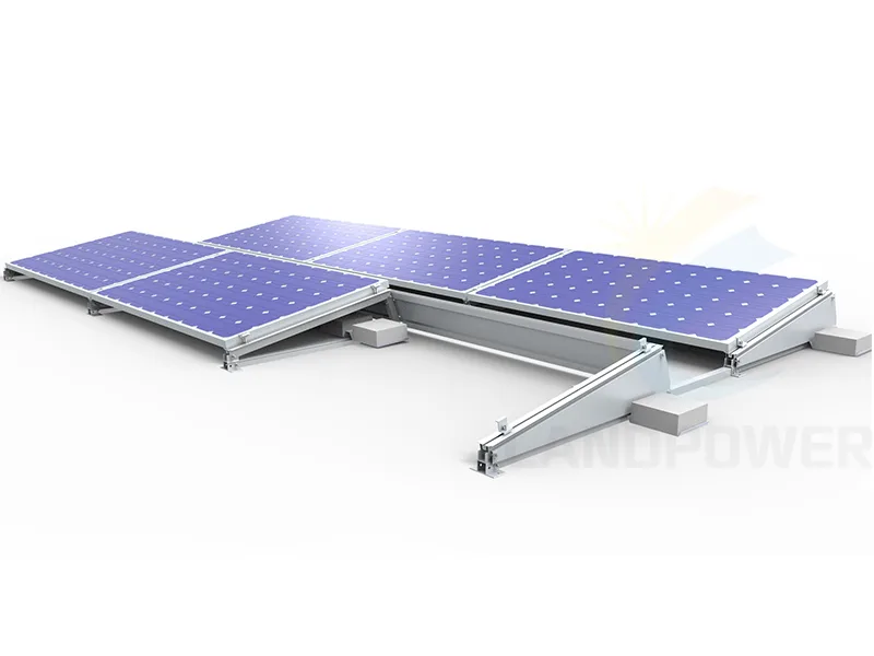
Ballasted Flat Roof Mounting Landscape
The Ballasted Flat Roof Mounting is design or solar panel panel installing in Landscape, Just few component,it is easy for installation,and they are cost-effective.
 Flat Roof Mounting System
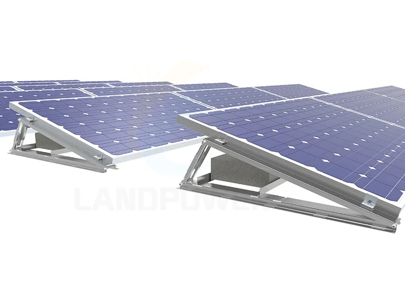
Flat Roof Ballasted Mounting V2
The Ballasted Flat Roof Mounting are easy solution to mount the panel,with anti-slide design,pre-assembled triangle,they are less components for easy to keep store.
 Flat Roof Mounting System
Flat Roof Solar Mounting Two Row Landscape
The Flat Roof Mounting is design for two row solar panel installation on flat roof,the are with triangle and mid clamp,end clamp etc,less components.Both for residential and commercial installation.